SUSTAINABLE CONSTRUCTION – AN EXPERIMENT WITH MECHANICAL JOINTS FOR GLUED LAMINATED TIMBER
The heavy frame structure of a shopping centre in the town of Hustopeče
The article deals with the analysis of rotational stiffness of a semi-rigid timber connection formed by a system of two glulam props and a crossbar. For this, pin-type metal mechanical fasteners were used. A combination of bolts and pins was tested together with all-threaded screws. The subject of the research and its motivation was replacement of these commonly used fasteners with more modern ones in order to improve the load-bearing capacity of this type of connection, and also to shorten and simplify the assembly time. Each of these two types of connection was subject to loading up to the level of 60, 80 and 100 % of the ultimate limit state. Subsequently, the rotational stiffness for each load level was determined after five cycles of loading and unloading. The obtained results of experimental testing were compared with the analytical assumption according to the currently valid code and were applied to connections and details of a one-storey heavy frame of a department store in the town of Hustopeče. The roof structure of the department store was designed for high loads and possible dynamic effects from the operation of a playground.
1. EXPERIMENTAL PHYSICAL ANALYSIS TO VERIFY THE BEHAVIOUR OF JOINTS AND DETAILS OF LOAD-BEARING PARTS OF THE STRUCTURE
DESCRIPTION OF THE STRUCTURE AND ITS GEOMETRY
The structural system of the experiment consisted of a semi-rigid connection of two posts and a crossbar. The connection was made by means of metal mechanical pin-type fasteners. Overall, two identical structural systems were created, with the only difference being the fasteners used. Experiment A contained a combination of bolts and pins as fasteners, and the other, experiment B, used all-threaded screws. Glued laminated timber of the declared GL24h class was used for the structure. To verify the properties of the wood, partial tests were created, which were already published in the Johanides 2022 article [1]. The post segment had a cross-section of 100 x 300 mm and the crossbar segment had a cross-section of 100 x 300 mm. The tensile strength of the material of fasteners has also been experimentally verified in the above-mentioned article. In experiment A, a combination of bolts and pins, steel grade 10.9, was used. The outer diameter of the threaded bar was 8 mm, the inner diameter was 7.25 mm. The bolt was 360 mm long and the length of the pin was 300 mm.
In this experiment, the fasteners were pre-drilled with an 8 mm drill. The idea was to create a connection without initial slip. The material of the fasteners in experiment B, the all-threaded screws, was steel grade 10.9. The outer diameter of the screw was 8 mm, the inner diameter of the screw was 5 mm and the length was 300 mm. This fastener was pre-drilled with a 5 mm diameter drill, also to minimize the initial slip in the connection.
The positions of the fasteners in both experiments were identical. Ten fasteners were arranged on one symmetrical circle with a radius of r = 90 mm. The positions were determined according to Koželouh 1998 [2], see Figure 1.
An external steel structure was built to provide boundary conditions for the experimental tests. A diagram of the experimental test itself is shown in Figure 2.
DESCRIPTION OF THE LOADING PROCESS AND LOCATION OF DISPLACEMENT SENSORS
The aim of the static cyclic tests was to investigate the behaviour of the frame connection at different load levels and, based on the data obtained, to determine the rotational stiffness values for individual load levels.
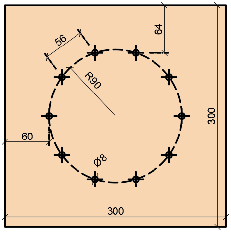
Fig. 1 - Arrangement of fasteners
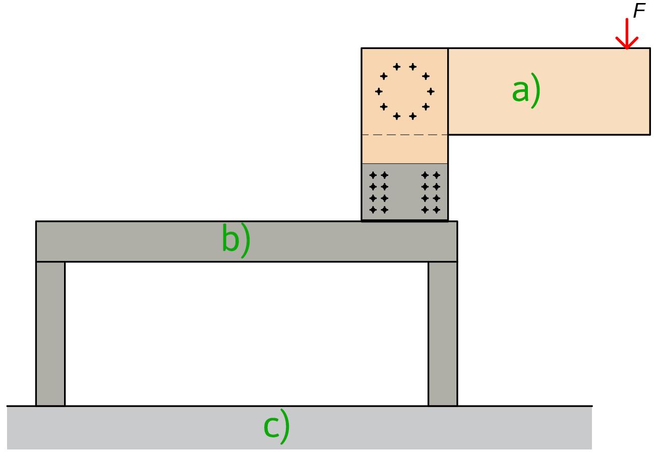
Fig. 2 - Schematic representation of the experiment: (a) investigated frame connection, (b) steel structure, (c) reinforced concrete floor
The idea of such testing is based on a practical requirement. This means that in practice, civil engineering structures are designed for limit states. In a real built-in structure, the ultimate limit state value must not be exceeded, as there would be a risk of permanent damage to the load-bearing structure or its collapse. Therefore, the rotational stiffness of the connection beyond the ultimate limit state has not been investigated. Three load levels were selected for experimental testing – 60, 80 and 100% of the ultimate limit state value.
The values of rotational stiffness of the semi-rigid connection were obtained by separating the individual external effects. The first external factor influencing the connection rotational stiffness was the connection of the lower part of the posts with the steel structure. A horizontal sensor, S2, was installed to obtain the inclination of the post from the steel structure, Figure 3.
The second component were the individual deformations of the segments of the structure. Their deformation could be calculated using the force method. Subtracting the individual deformation components from the total deformation obtained from a vertically oriented sensor, S1, Figure 3, we get the actual value of the deformation caused by the rotational stiffness of the semi-rigid connection.
EXPERIMENTAL TESTING
The experiments were carried out in the Centre for Building Experiments and Diagnostics of VSB – Technical University of Ostrava, Czech Republic. Figure 4 (top) shows experiment A (a) with the bolt and pin combination, Figure 4 (bottom) shows experiment B (b) with the full-threaded screws before static cyclic loading. The load was applied to the connection using a steel cylinder with a diameter of 50 mm. A 10 mm thick rubber pad was inserted under this cylinder to prevent local damage to the wood during loading.
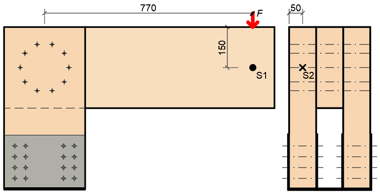
Fig. 3 - Location of deformation sensors, front view on the left, side view on the right.
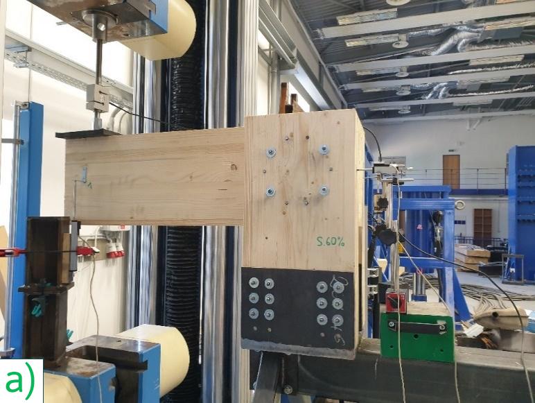
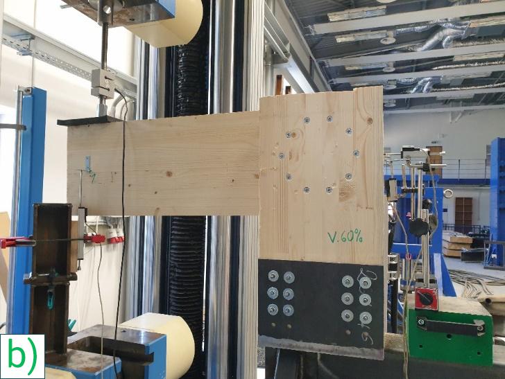
Fig. 4 - Experimental samples: (a) experiment A with the bolt and pin combination, (b) experiment B with the full-threaded screws.
Table 1 - Result values of rotational stiffness.
|
Method |
Type of fastener |
|
Value [MNm/rad] |
Comparison [%] |
|
ČSN EN 1995-1-1 [3] |
Bolts and pins |
kr,u,EC5 |
0.323 |
- |
|
kr,u,EC5,1 |
0.299 |
-8 |
||
|
kr,u,EC5,2 |
0.293 |
-10 |
||
|
kr,test,60 |
2.198 |
+85 |
||
|
kr,test,80 |
1.055 |
+31 |
||
|
kr,test,100 |
0.404 |
+20 |
||
|
ČSN EN 1995-1-1 [3] |
All-threaded screws |
kr,u,EC5 |
0.323 |
- |
|
kr,u,EC5,1 |
0.206 |
-57 |
||
|
kr,u,EC5,2 |
0.202 |
-60 |
||
|
kr,test,60 |
0.386 |
+16 |
||
|
kr,test,80 |
0.313 |
-3 |
||
|
kr,test,100 |
0.896 |
+64 |
RESULTS OF EXPERIMENTAL RESEARCH
Table 1 shows the values obtained from the experiment. These are compared with the design values obtained using the ČSN EN 1995-1-1 [3] code. The value for each load level was obtained by averaging the values from five load cycles. In this comparison, the value of kr,u,EC5 0.323 MNm/rad is taken as a reference value. This value was obtained by substituting the standard material properties into the formula for the calculation of the slip modulus according to the above-mentioned code. The next value in the table is kr,u,EC5,1. This value was obtained using the actual measured diameter of the fastener core and the actual measured wood density. The last value of kr,u,EC5,2 is the value obtained using the actual diameter of the fastener core and the standard value of wood density according to its strength class.
Figures 5 and 6 show the ‘load - rotational stiffness’ diagrams of the individual connections. This figure also shows the rotational stiffness values calculated for the ultimate limit state (ULS) and the ultimate limit state without partial safety factors applied (ULS 1).
Figure 7 shows ‘load - rotational stiffness’ diagrams for individual fasteners. It is clear from the diagram that the rotational stiffness of the connection with screws increases slightly with increasing loads, while the rotational stiffness decreases for the combination of bolts and pins.
Figure 8 shows a numerical model of the tested frame corner. It is a component for a heavy frame. The aim of these tests (different types of fasteners were used both in the corner itself and in external connections to steel members) was to determine the rotational stiffnesses and to perform the overall analysis of the behaviour of this type of connection.
Figure 9 shows photos from the laboratories of the Faculty of Civil Engineering at VSB Technical University of Ostrava.
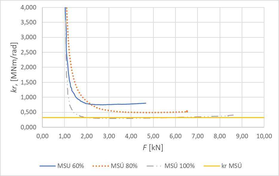
Fig. 5 – ‘Load - rotational stiffness’ diagram, combination of bolts and pins.
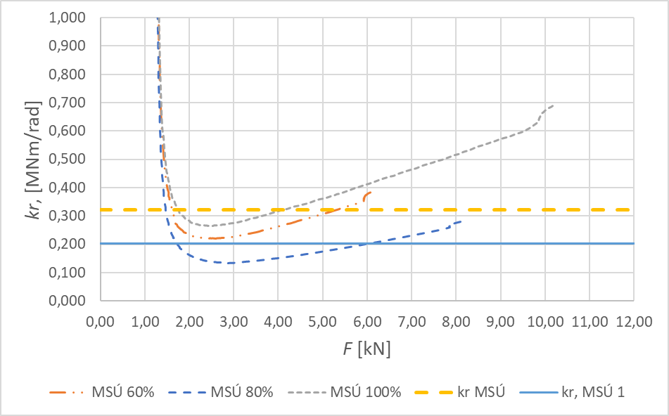
Fig. 6 – ‘Load - rotational stiffness’ diagram, all-threaded screws.
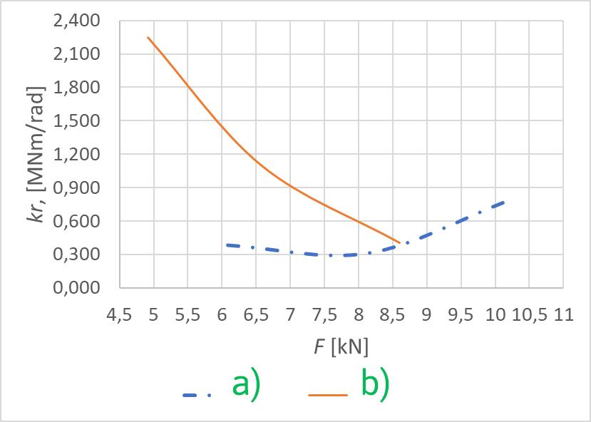
Fig. 7 – Comparison of the rotational stiffness for individual fasteners: (a) screw, (b) bolt
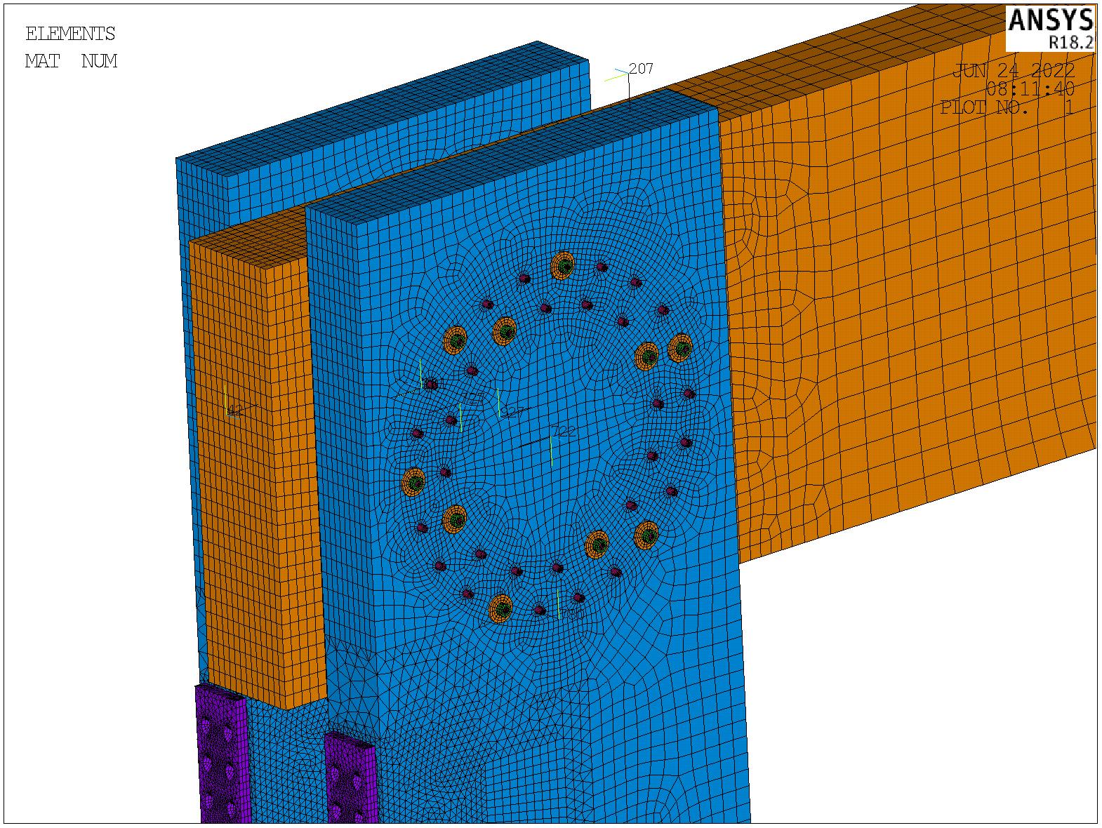
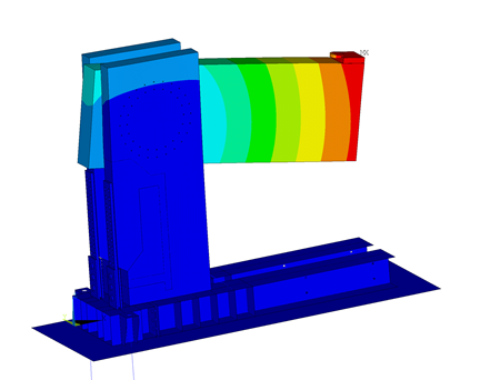
Fig. 8 – (a) geometry and finite element meshes of the frame corner, (b) total deformation of the analysed structure.
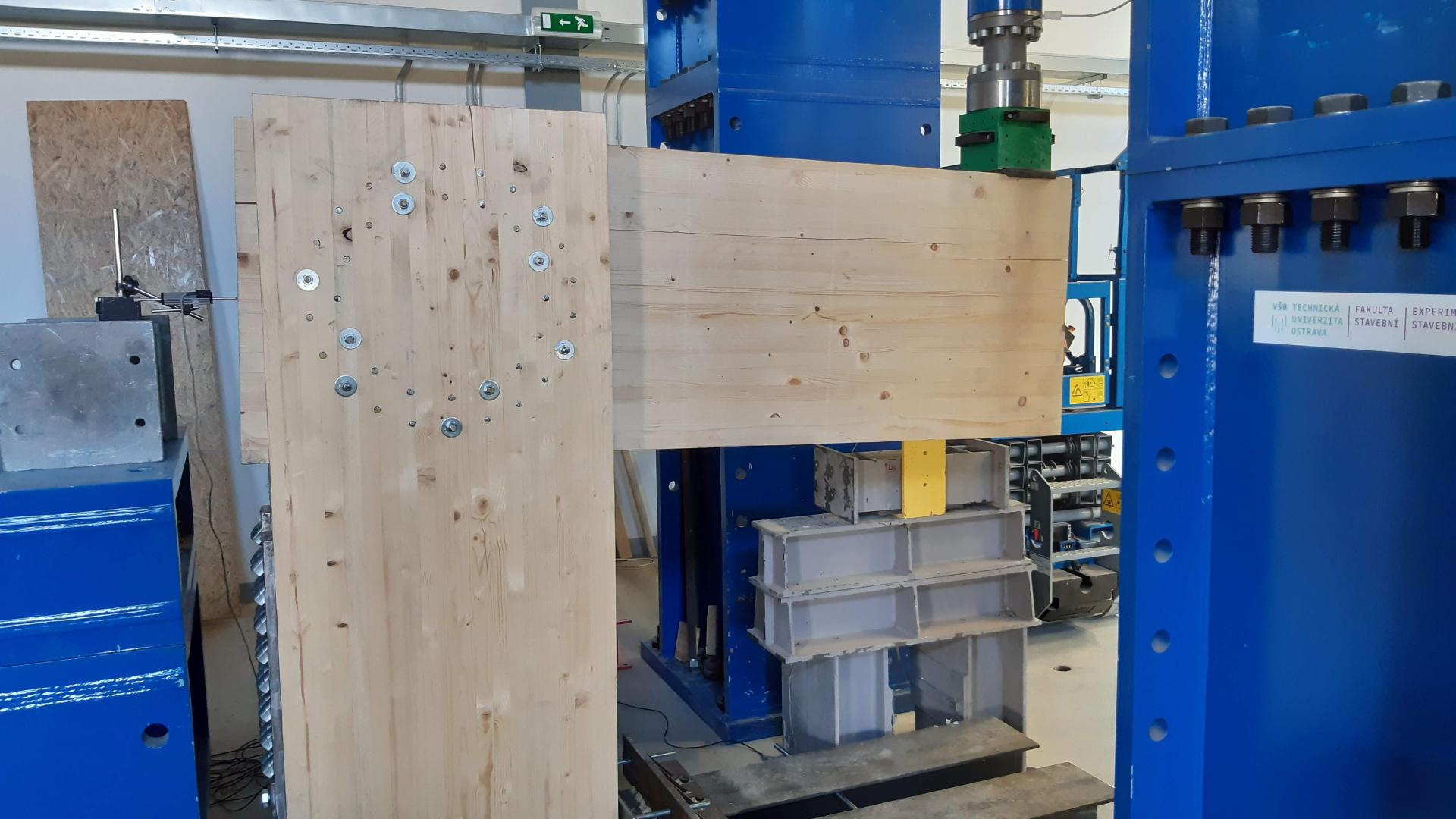
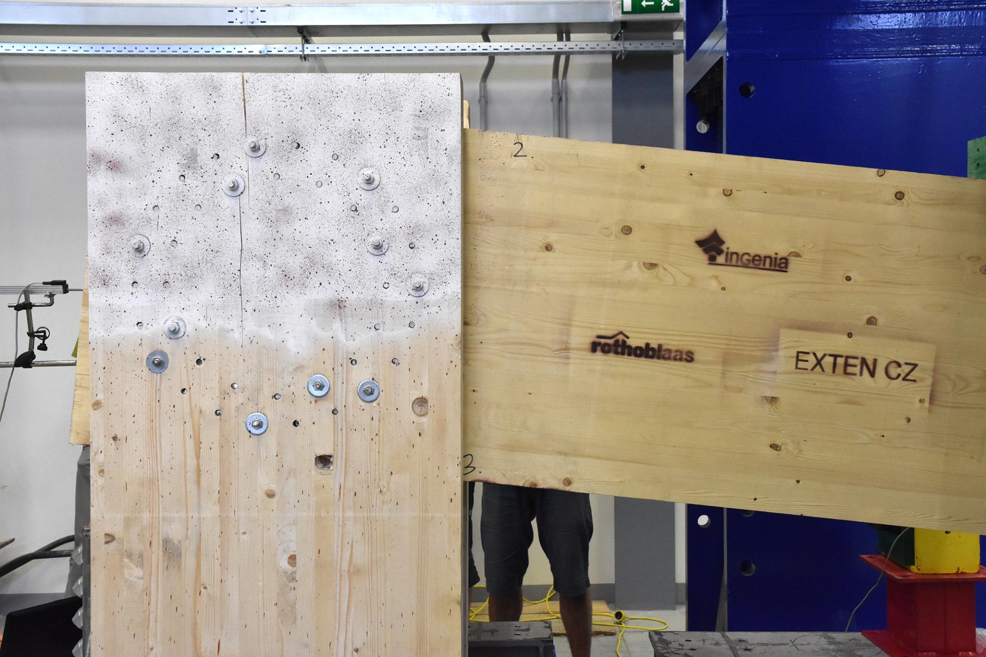
Fig. 9 – (a) preparation of the frame corner test, (b) example of the frame corner deformation after loading.
CONCLUSIONS
Experimental testing of a connection made of a commonly used combination of bolts and pins (experiment A) proved the safety and reliability of the connection when loaded to the ultimate limit state. From the point of view of rotational stiffness, this connection gives, during the entire loading period, values higher than the code assumes for the ultimate limit state.
Experimental testing of a connection made of all-threaded screws (experiment B) also proved the safety and reliability of the connection when loaded to the ultimate limit state. From the point of view of rotational stiffness, this connection does not reach values higher than the assumption of the code for the ultimate limit state for the load level of 80% of ULS. This experiment suggests that in order to obtain a more accurate result of the rotational stiffness according to Eurocode 5 [3], it is necessary to use the diameter of the fastener shank to calculate the slip modulus. Alternatively, the diameter of the fastener shank and the actual measured wood density can be used. Since it is difficult, from a practical point of view, to obtain the actual measured wood density, the data obtained in this paper indicate that the sufficient accuracy can be obtained using the diameter of the fastener shank and the code-defined value of wood density.
The issue of determining the load-bearing capacity of timber connections according to the European standards for the design of timber structures Eurocode 5 [3] is continuously evolving. This trend could also be supported by the proposed experiments, which focused on determining the rotational stiffness of a semi-rigid connection of a wooden crossbar and a post created using mechanical pin-type fasteners.
In terms of rotational stiffness, the data from the experiments can be used for practical design of this type of semi-rigid connection. The author, Marek Johanides, has published separate articles on resistance [4], ductility [1] and rotational stiffness [5] of this type of connection.
The advantage of wood is its renewability and character, which people have known and sought for millennia.
Considering its density, the wood mass has very good strength properties longitudinally with the fibres. If the structural element is massive, the fire resistance is also high, and if it is supplemented with passive and active fire protection elements, it is possible to build multi-storey wooden houses, like for example in Brumunddal, Norway.
Wood, as a natural grown material, is susceptible to biological decay and attack (wood-decaying fungi and insects). If the timber and its connection details are sufficiently protected, these structures have the potential to last for hundreds of years (the Kapellbrücke bridge, Switzerland).
2. APPLYING THE POSSIBILITIES OF NUMERICAL MODELS ON THE REALIZED CONSTRUCTION OF THE HUSTOPEČE COOP DEPARTMENT STORE
HEAVY FRAMES IN SUSTAINABLE CONSTRUCTION
Heavy wood-based frames are nowadays a sought-after option for multi-storey or heavy buildings. This is mainly driven by the tendency to have the industry, of which the construction industry is a part, as sustainable as possible, especially with regard to resources and energy, including environmental friendliness and renewable resources. Wood is a natural material and as such it has its advantages as well as properties that need to be improved to achieve the required parameters given by the type and purpose of the building.
With the development of advanced wood processing (GLT, CLT, etc.) supplemented by the development of details of high-capacity connections (steel, epoxy resins, glass fibres and combinations of these materials), together with powerful numerical simulations supplemented by normative experience and physical testing, it is now possible to design and optimize the building as a whole, thus enabling wood-based buildings to achieve new volumes, shapes and forms. Figure 10 shows a visualization of a possible practical use of the roof of the designed frame.
The aim of this article is to introduce the possibilities of heavy frames. In general, according to the static system, load-bearing structures can be divided into frame, wall and truss systems. The frame system is inherently the least rigid, and this applies even more to connections in timber structures. The wall system is very rigid and can be considered for high-rise buildings (reinforced concrete cores of skyscrapers). The truss system is relatively light, features good rigidity and the connection between the individual elements (with high nodal forces accumulated here) is, similarly to frame systems, also the dominant point. With a suitable geometry, the wall system does not lead to such high nodal forces in connections and, as a result, does not produce such high local stress in the connection details. Figure 11 shows a design of a hall with dimensions of approximately 30.6 × 46.3 × 6 m, the ground plan is dominantly rectangular with side staircases. The hall is connected to a side service structure of the hall facilities.
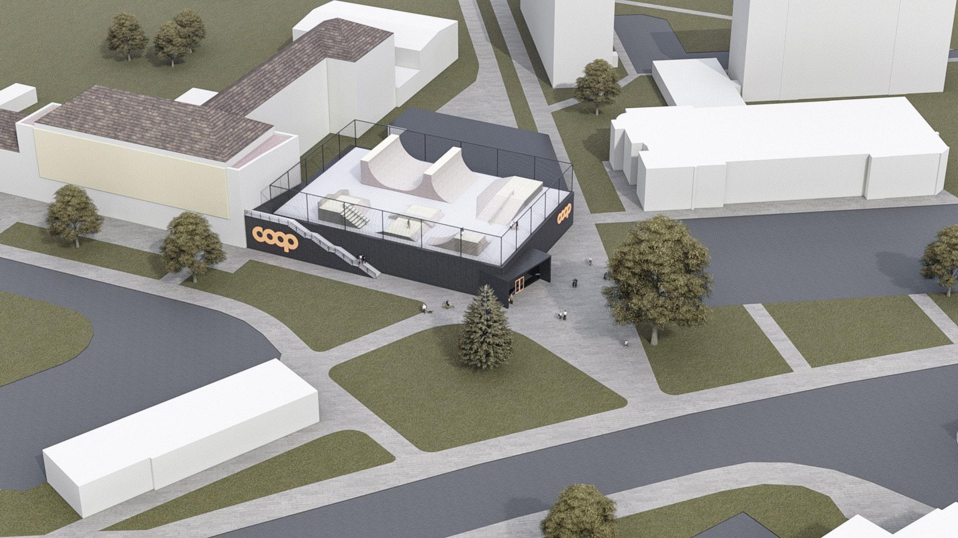
Fig. 10 – Unrealized visualization of the Hustopeče COOP department store.
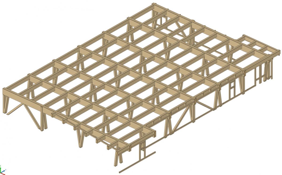
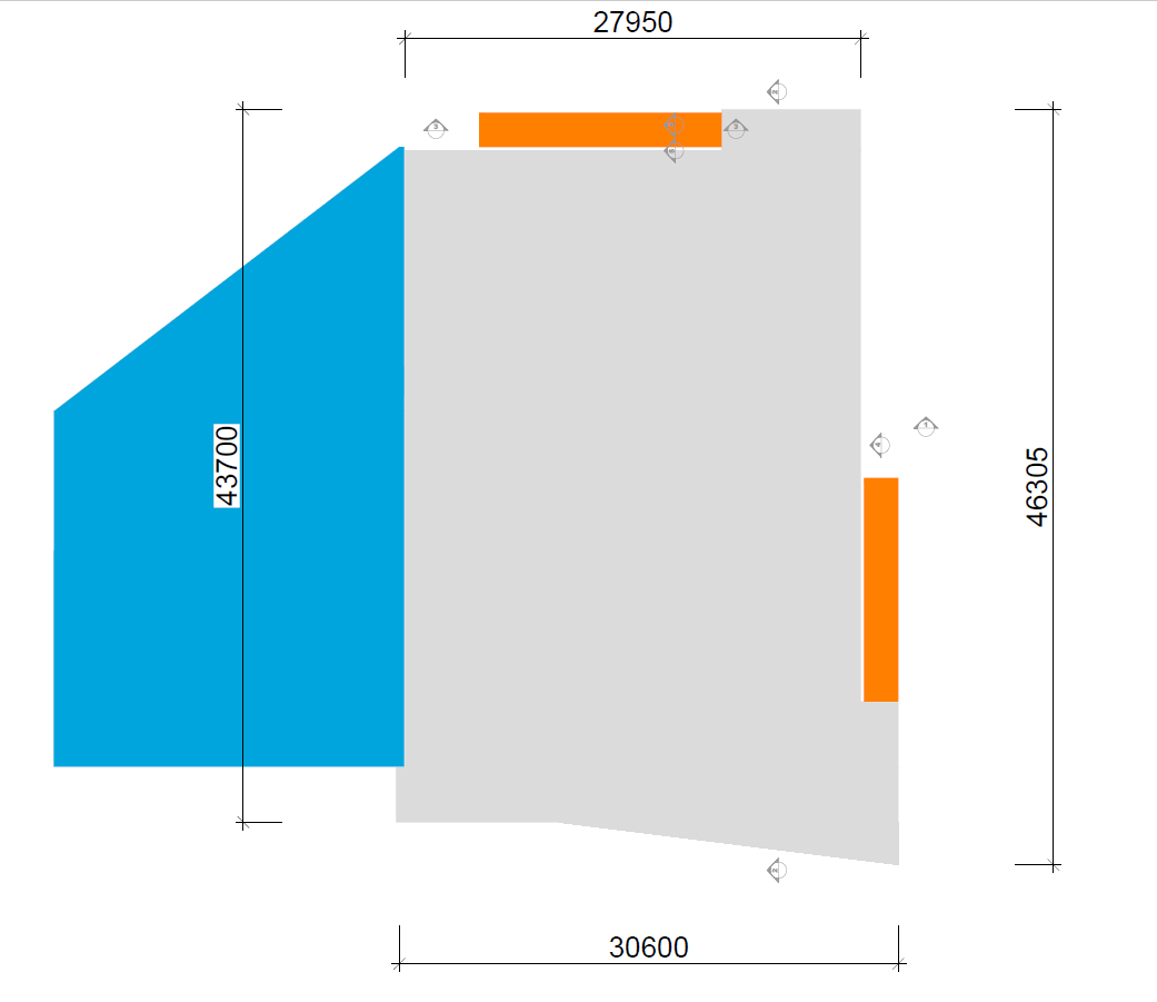
Fig. 11 – Combined system, diagram of the heavy frame – frames and trusses of COOP Hustopeče.
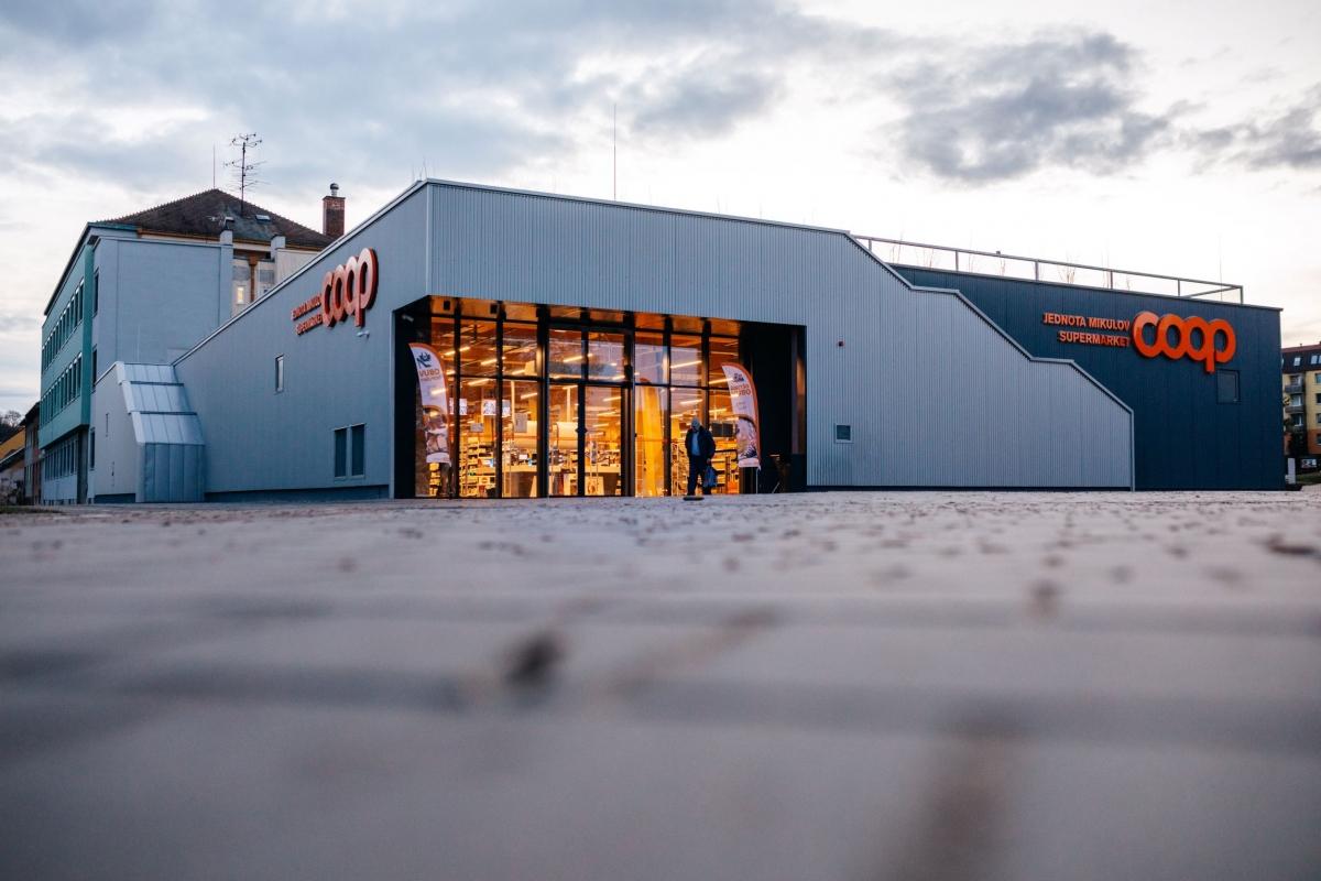
Fig. 12 – View of the entrance to the department store.

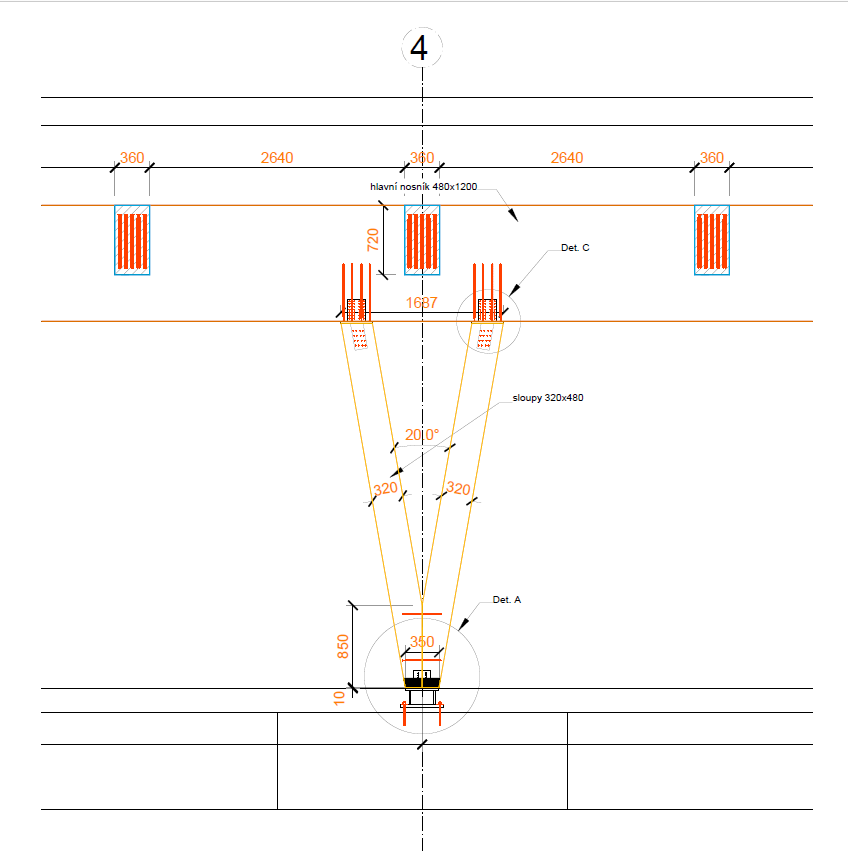
Fig. 13 – Interior of the department store in operation (left), detail of the "V" column anchoring (right).

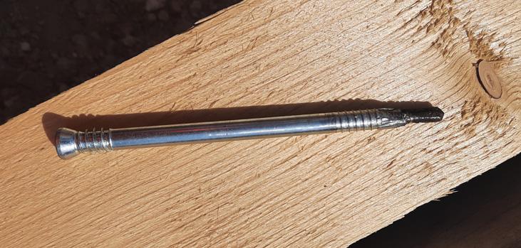
Fig. 14 – View of the frame elements (left), the screw for wood and steel (right).
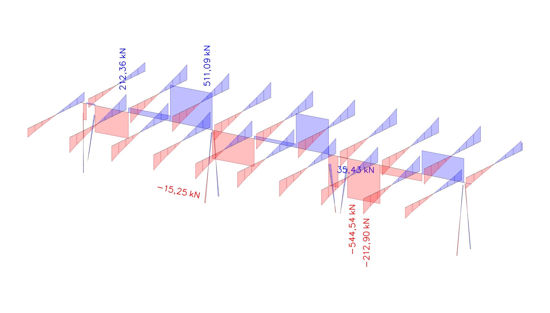
Fig. 15 – Internal forces in the load-bearing elements of the frame.
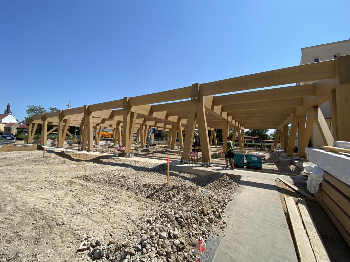
Fig. 16 – Assembled main load-bearing structure of the department store hall.
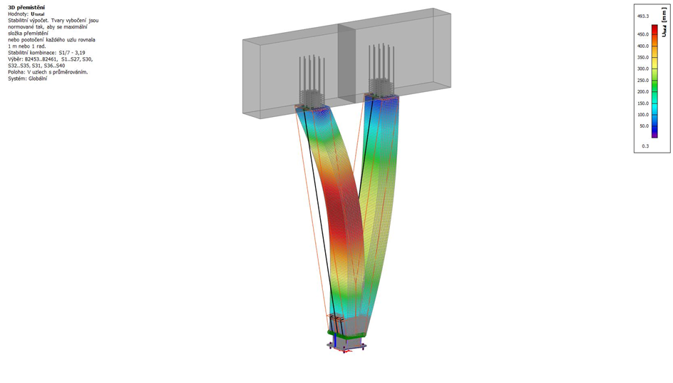
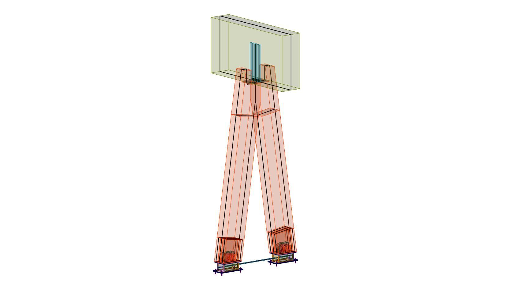
Fig. 17 – Numerical model of the load-bearing elements of the frame.
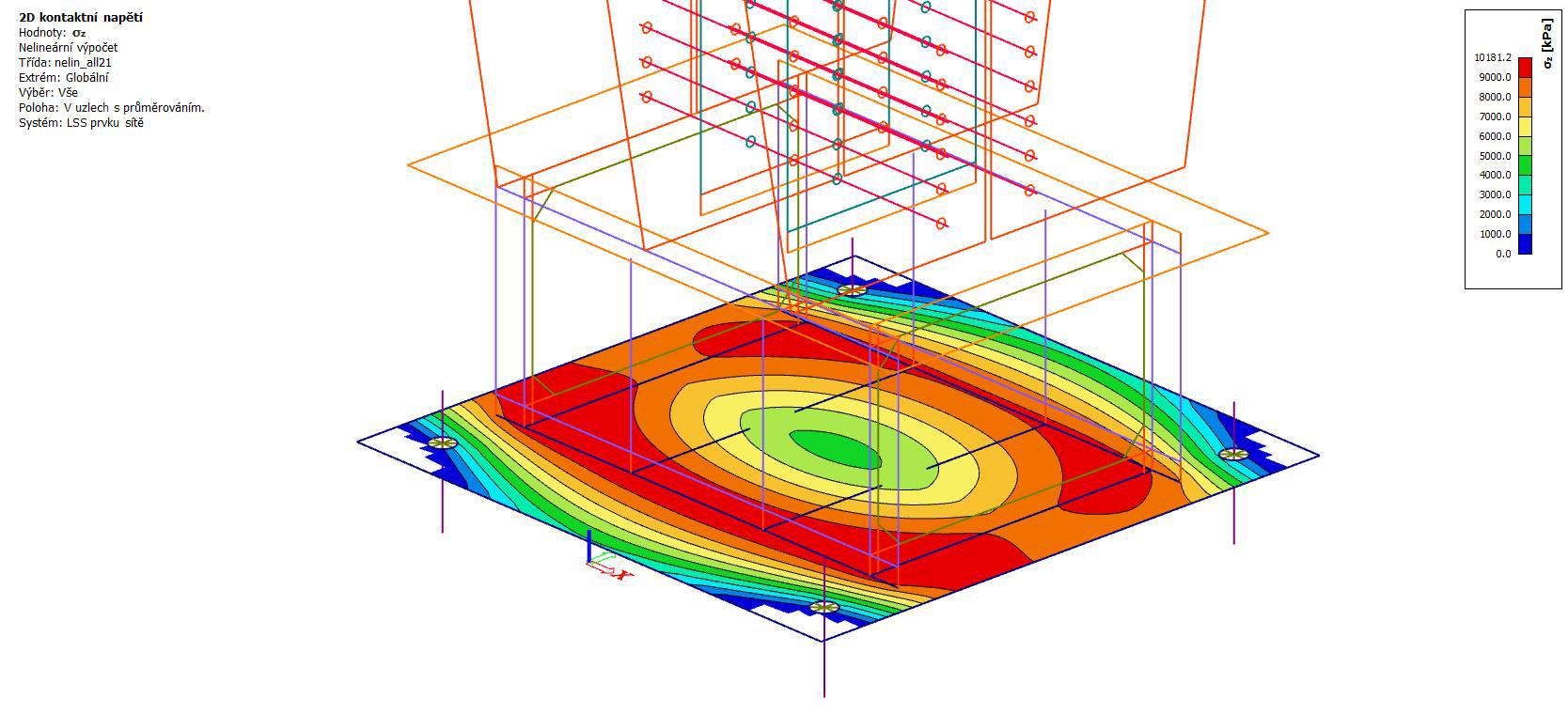
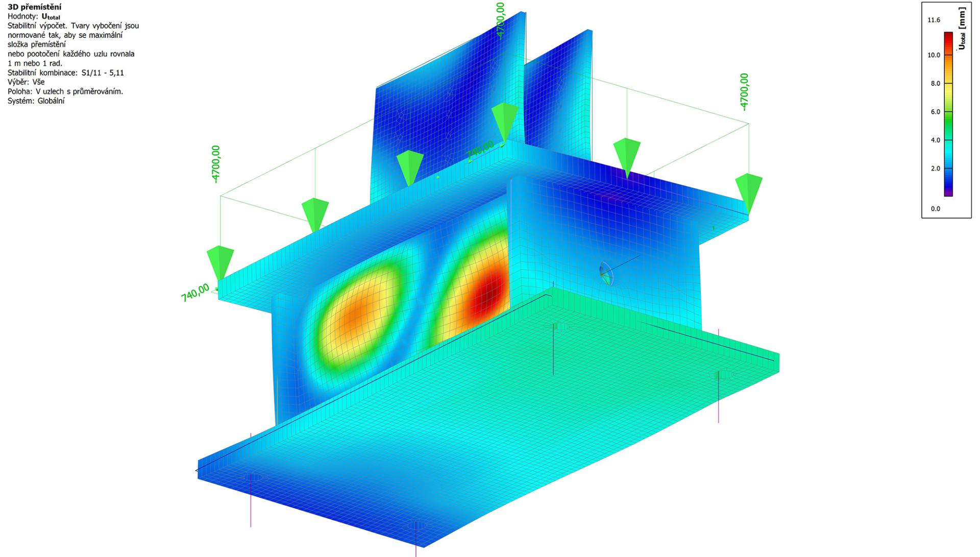
Fig. 18 – Internal forces in the load-bearing elements of the frame.
COOP DEPARTMENT STORE IN HUSTOPEČE
It is a single-storey shopping mall building with a heavy roof designed as a skate park. The main load-bearing system is formed by columns and a rigid roof slab with beams and joists. Selected wooden elements are glued and have the width of 480 mm. The spatial rigidity of the structure is ensured by "A" and "V" columns, which are arranged in rectangular grids with a rigid roof plane. The columns are primarily subjected to compression and tension. The frame corner is formed by a closed triangle. Figure 12 shows the cladded structure of the department store hall.
The left part of Figure 13 is the view of the furnished interior of the department store. Here one can see the incorporation of the load-bearing structure into the scheme needed for the operation of the store. Despite its massiveness, the structure offers a natural impression within the space with an emphasis on the natural character of the main elements of the hall structure. Given the dimensions of the elements and hidden connections, the structure will feature high fire resistance. The right part of Figure 13 shows the column, its anchoring and connection to other elements of the hall structure.
Figure 14 – on the left side of the photo we can see one of the main elements of the wooden "V” frame; frame system connected to the joist. The joist, 480 × 1,200 mm in size, is a glued element made of glued laminated timber of the GL28h class. The joist is also connected to glued Gl28h beams with a cross-section of 360 × 720 mm. The beam is anchored to the joist using SFS all-threaded screws with a diameter of 13 × 500 mm, with 10 screws per one connection. The connection is designed for shear force of approximately 211 kN from the roof load, including climatic and variable loads.
The picture on the right shows a mechanical fastener for wood and steel. With this self-drilling pin, timber elements can be connected to steel plates without pre-drilling. The connection features a high load-bearing capacity and rigidity. These connections were used in the heads and bases of the columns.
Figure 16 shows the main load-bearing system of the wooden single-storey frame before cladding. Figure 17 then shows numerical models of the main load-bearing elements. The left image depicts a selected stability eigenmode for the specified load. This eigenmode is determined by the local deflection of the column. The middle picture shows the used fastener - all-threaded screw - which was used to increase the load-bearing capacity of the wood in the compression perpendicular to the grain, to transmit shear forces (see Figure 15) and to clamp together the wood mass in tension perpendicular to the grain. The right picture shows an "A" type load-bearing frame with truss behaviour.
This picture reveals how the system of timber and steel elements is numerically modelled. The numerical model was composed of shell and beam elements [7], taking into account the foundation and physical and geometric nonlinearity. Furthermore, also the slip in connections and structural nonlinearity with imperfections are considered. Such a model can be analysed separately or as a part of a global model. If the separate model is incorporated into the global numerical model, the complexity of the solution increases. However, the interaction is more realistic, because the boundary conditions are given by the "real" modelling of the connection of the individual elements.
Figure 18 is a detail of the left structure from Figure 17, namely its base plate. The image on the left shows the contact stress in connection of the steel stirrup to the reinforced concrete base. The contact stress here is approx. 10.20 MPa for a compressive force of approx. 1,144 kN. The image on the right side shows the stability eigenmode for the load that should generate the maximum compression. Local buckling of the longer web of the closed steel box can be clearly seen. The eigenmodes mentioned here are around 2.7 times the input load. The advantage of complex numerical models is that the calculation of nonlinear stability modes takes into account global stiffness.
Figure 19 shows a part of the load-bearing system of the timber frame selected from the entire numerical model. This numerical model is composed of volume and beam finite elements. The problem is a contact one, and it takes into account wood orthotropy with bilinear stress-strain diagrams for wood and steel.
The left part of Figure 20 shows the finite element mesh of the joist and beam with the steel screws. The connection is made via contacts with friction and slip. The numerical model shown in the figure is a part of the global model, see Figure 19. The place for meshing of the analysed detail of the shear connection was so chosen that the connection is subject to approx. 211 kN which is the maximal force in the beam model. The picture on the right is a detail of the screws that are installed in the joist and beams and that form a shear connection.
The picture shows stress reaching approx. 1,019 MPa in the area of the beam and joist connection. This part of the connection behaves as a truss, which corresponds to the assumptions applied in the design of this connection. This connection has been used in construction practice already for decades.
Figure 21 – the left part shows shear stress in the joist element with the dimension of 480 × 1,200 mm. The shear stress in the connection of the beam and the joist reaches a value of about 2 MPa. For solid wood and this type and direction of loading, the code prescribes the characteristic value of stress 2.7 MPa. The value of the shear resistance for the mentioned loading ranges from 3 MPa to 6 MPa. The right picture shows stress in the 360 × 720 mm beam. The behaviour is similar to the behaviour shown on the left picture for the joist. The analysis also took into account possible inaccuracies in the contact connection between the joist and the beam. Variants of numerical models considered both the immediate contact between the joist and the beam, and a gap that will be between the elements of the beam and the joist even after loading.
The analysed models revealed that the influence of the contact between the beam face and the joist surface does not have a significant effect on the stress in the screws up to approximately 7% of the Von Mises stress. When the beam and the joist are in full contact, there is a noticeable increase in the contact stress perpendicular to the grain, which can reach 5.0 MPa locally.
Figure 22 depicts the stress distribution perpendicular to the grain. For the load at the end of the beam of 211 kN, the local maximum of the tensile stress perpendicular to the grain is 2.70 MPa and the local minimum of the compressive stress perpendicular to the grain is 5 MPa. These are values at the limit of the wood strength. Due to their nature, this is partly a numerical extreme caused by simplifications in modelling and by the choice of a material model that cannot fully describe the behaviour (anisotropy) of wood. In principle, however, these extremes arise and accumulate in the area where the screws cross each other and pass from the beam to the joist. The bottom stress in the joist perpendicular to the grain is given by the numerical model, which takes into account the instant contact between the beam and the joist and its prying into the joist around its bottom edge. Here, due to friction, the load of the screws also changes slightly, because they are constrained to rotate around a specific point. Figure 22 - the right part depicts the deformation of the beams and the joist. The minimum is approximately 9 mm and the maximum 12 mm. The mutual slip between the beam face and the projection of the beam face onto the joist caused by the maximum shear force of 211 kN per connection is approximately 0.977 mm.
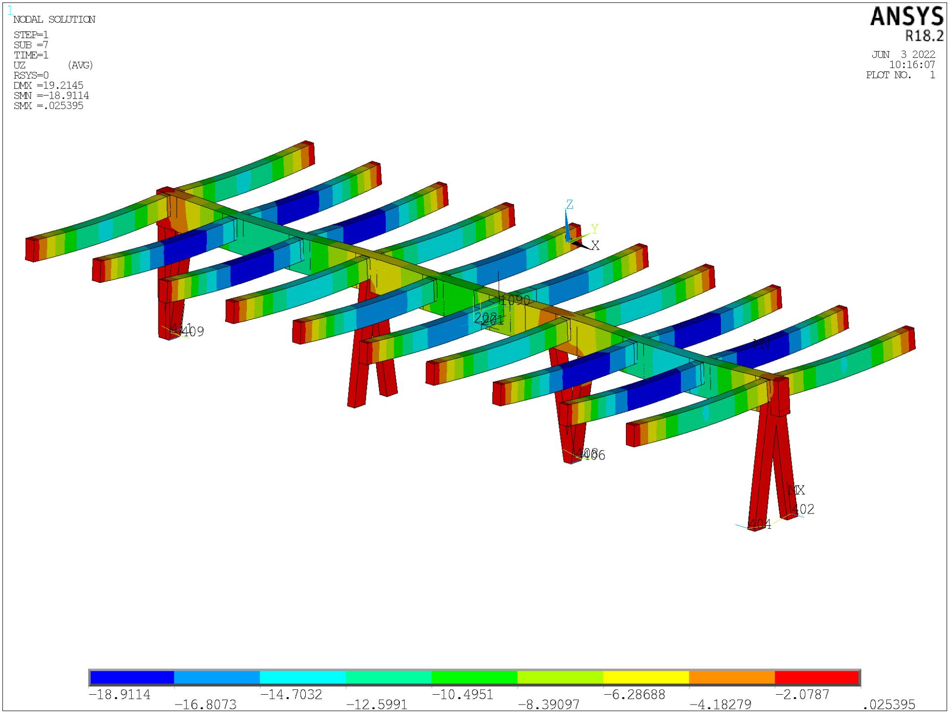
Fig. 19 – Deformation of a selected joist including the shear connection detail, ANSYS model [6].
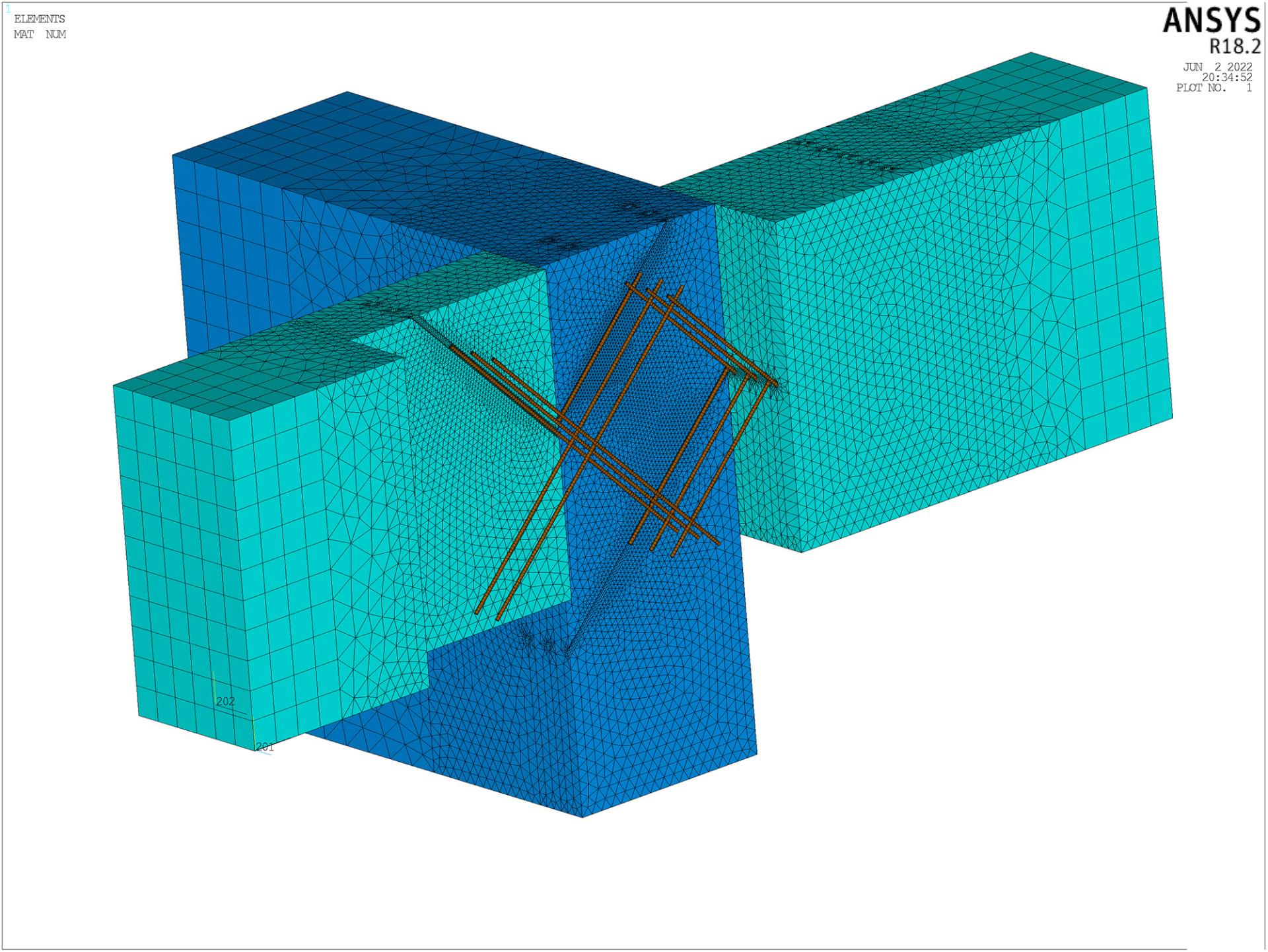
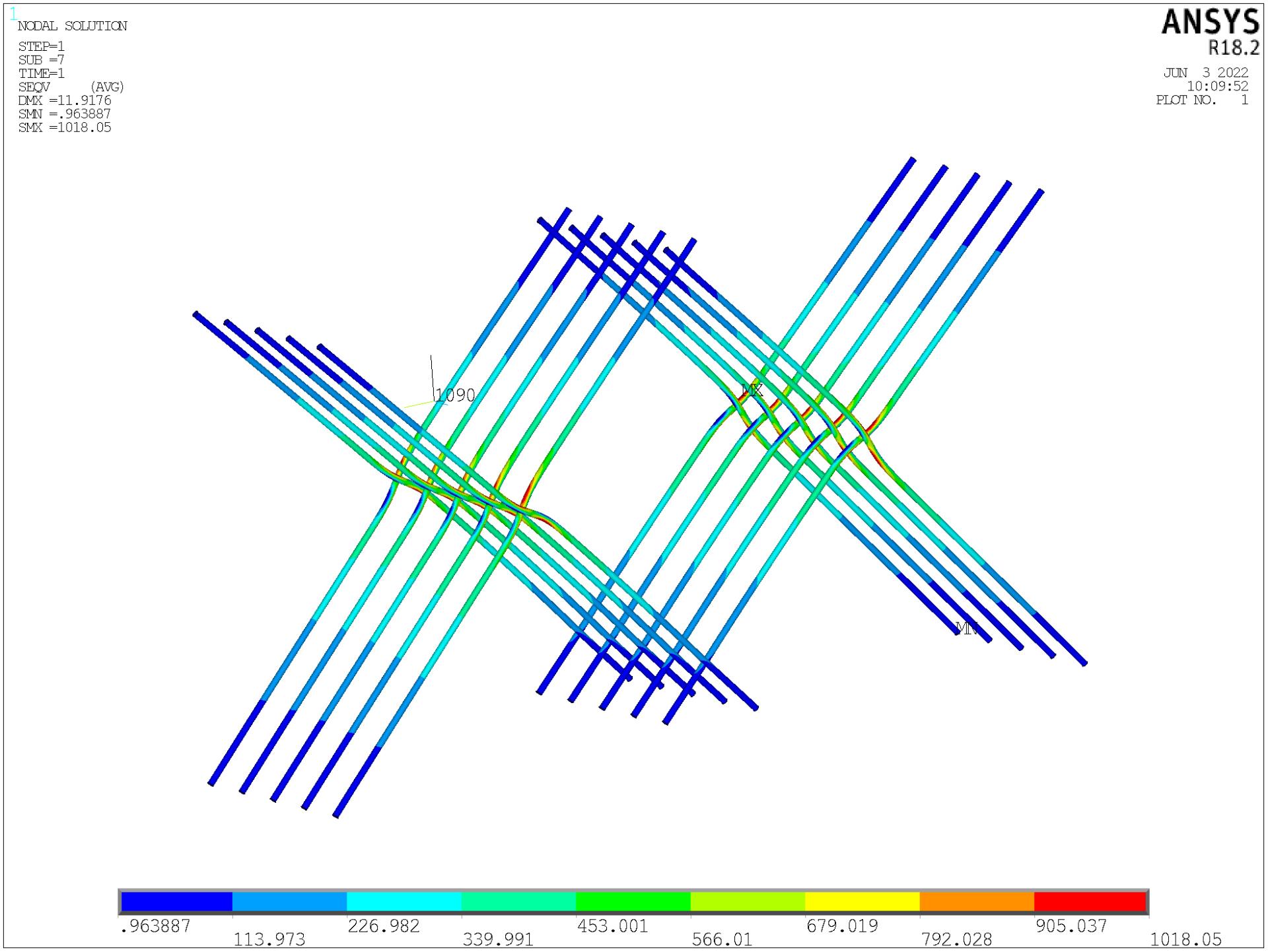
Fig. 20 – Detail of the numerical model of the finite element mesh and screws.
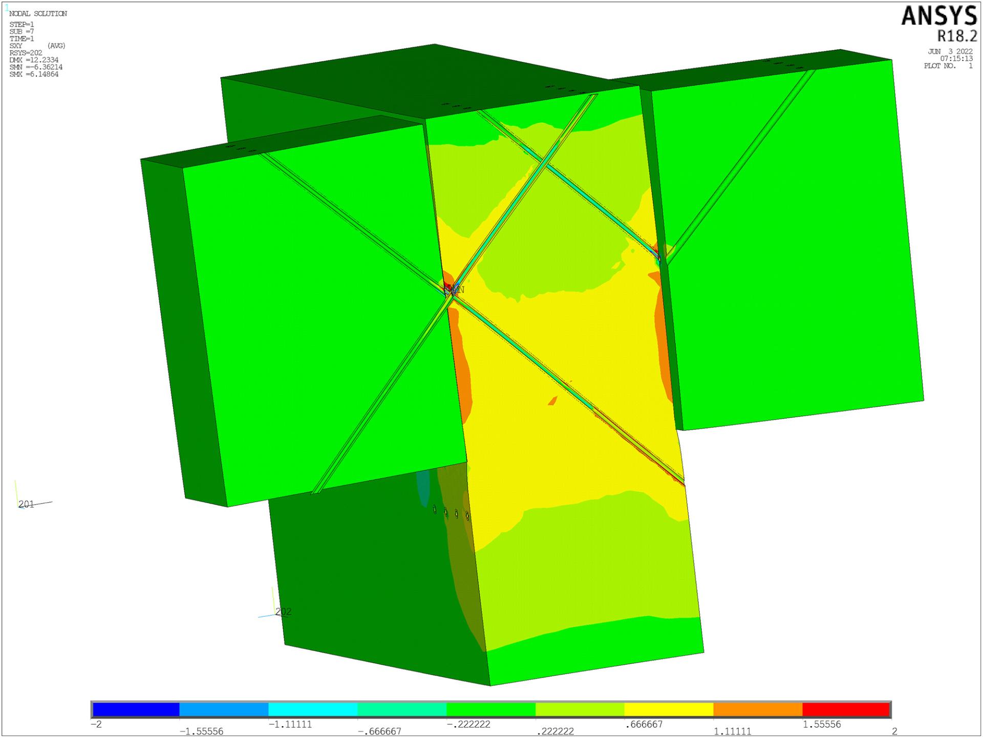
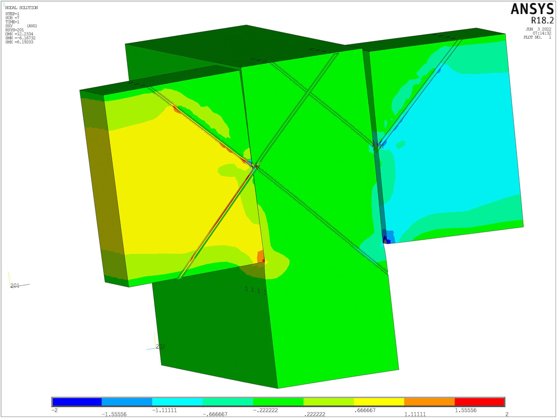
Fig. 21 – Shear stress in the joist and beam in the selected connection detail.
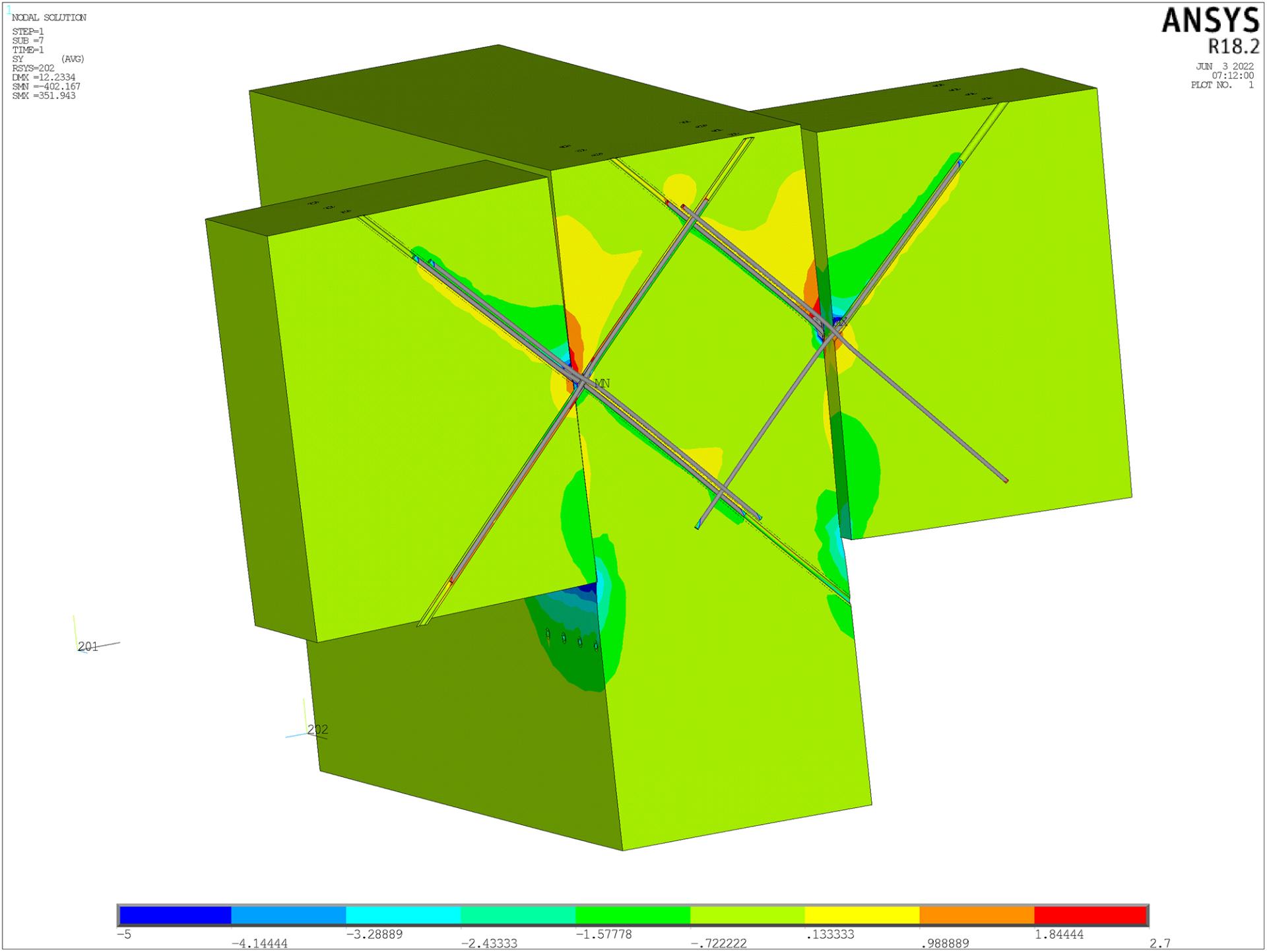
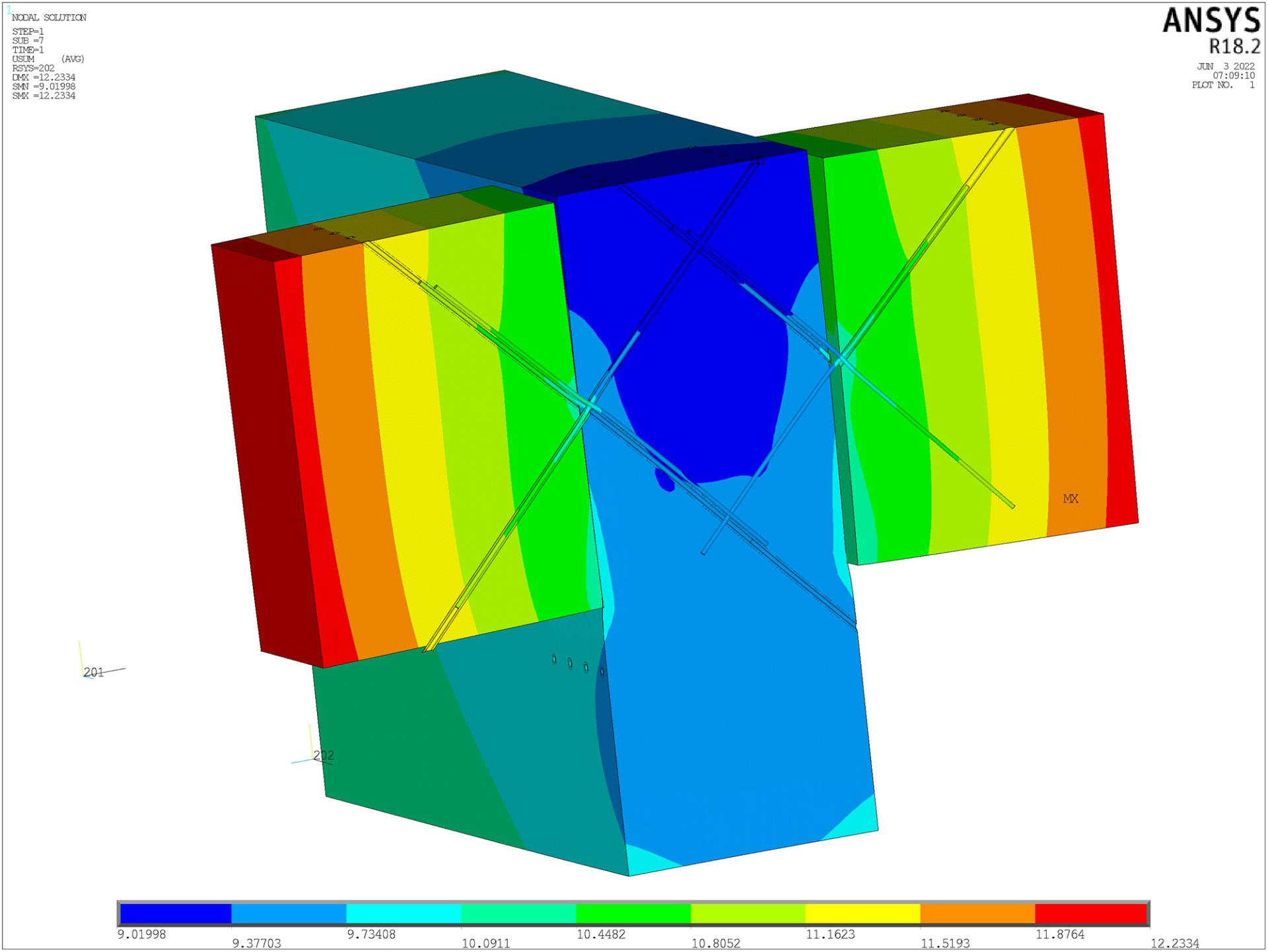
Fig. 22 – Detail of the numerical model, tensile stress perpendicular to the grain and deformation of the connection.
APPLICATION OF NUMERICAL METHODS IN PRACTICE
To summarize the analysis of heavy frames and their details, the application of numerical methods is advantageous for details and structures that are new in their nature or are subject to high load and their geometry and method of anchorage are less known. Numerical methods must be supplemented by a code-defined method of solution, professional literature and, if necessary, also by physical testing. Consultations with senior experts in the field are also an essential part.
When this range of approaches to solving new types of connections and structures is available, it is possible to assemble complex structures and optimize their system and details so that their strength and stiffness are accompanied by an appropriate ductility response.
At present, when it is appropriate and necessary to take into account the state of the planet and its resources, without which our civilization is not able to survive in its current form, the development in the field of wood-based buildings can bring ecological and degradable materials that are not only beautiful, but also fully functional and able to withstand high loads. In this way, a wide area of construction industry can benefit, from family construction to building complexes to multi-storey high-rise buildings (examples include Scandinavia, Austria and England).
LITERATURE
[1] Johanides, M.; Lokaj, A.; Mikolasek, D.; Mynarcik, P.; Dobes, P.; Sucharda, O. Timber Semirigid Frame Connection with Improved Defor- mation Capacity and Ductility. Buildings 2022, 12, 583. https://doi. org/10.3390/buildings12050583.
[2] Timber Structures According To Eurocode 5; STEP 1: Design and construction materials; Translated by Bohumil Koželouh; KODR: Zlín, Czech Republic, 1998; ISBN 80-238-2620-4 (In Czech).
[3] ČSN EN 1995-1-1. Eurocode 5: Design of Timber Structures – Part 1-1: General – Common Rules and Rules for Buildings; Czech Standards Institute: Praha, Czech Republic, 2006.
[4] Johanides, M.; Lokaj, A.; Dobeš, P.; Mikolášek, D. Numerical and Experimental Analysis of the Load-Carrying Capacity of a Timber Semi-Rigid Dowel-Type Connection. Materials 2022, 15, 7222. https://doi.org/10.3390/ma15207222.
[5] Johanides, M.; Lokaj, A.; Dobeš, P.; Mikolášek, D. Numerical and Experimental Analysis of the Rotational Stiffness of a Timber Semi-Rigid Dowel-Type Connection. Materials 2022, 15, 5622. https://doi.org/10.3390/ma15165622.
[6] AnsysTM, available at www.ansys.com.
[7] Scia Engineer, available at www.scia.net.
Authors:
Ing. Marek Johanides, Ph.D., specializes in timber and steel structures with regard to numerical modelling supplemented by physical testing. He is a member of the Centre for Building Experiments and Diagnostics of VSB – Technical University of Ostrava, Czech Republic.
Prof. Ing. Antonín Lokaj, Ph.D., specializes in timber and steel structures with regard to applied research and development of connection details in combined structures. He is the Head of the Department of Structures and Vice-Dean for Development at the Faculty of Civil Engineering, VSB – Technical University of Ostrava, Czech Republic.
Ing. David Mikolášek, Ph.D., specializes in timber, steel and composite structures with regard to numerical modelling validated by physical testing. He is a member of the Department of Structures at the Faculty of Civil Engineering, VSB – Technical University of Ostrava, Czech Republic.
Ing. Pavel Dobeš, Ph.D., specializes in building structures, details with regard to their diagnostics, testing and calculations. He is a member of the Centre for Building Experiments and Diagnostics of VSB – Technical University of Ostrava, Czech Republic.
Ing. Pavel Vlček, Ph.D., specializes in the field of civil construction and inclusion of new knowledge about structural systems in construction practice. He is a member of the Department of Civil Engineering at the Faculty of Civil Engineering, VSB – Technical University of Ostrava, Czech Republic.
Ing. Robert Martinek is a specialist in the field of timber structures with a focus on the design, optimization and production of wooden details and structures. He works as the executive director at EXTEN CZ.
This article was published in magazine KONSTRUKCE 4/2023 (https://konstrukce.cz).